

Press Metal Machine: Complete Engineering Guide to Types, Selection, and CNC Press Brake Specifications
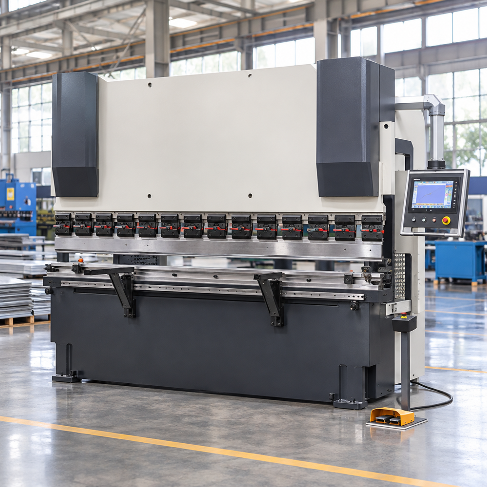
Selecting an industrial press metal machine requires navigating a crowded landscape of mechanical presses, hydraulic systems, and automated sheet metal bending machines. For fabricators, structural steel workshops, and tier-one automotive suppliers, choosing the right sheet metal forming equipment directly dictates cycle times, bend precision, and scrap rates. A modern press metal machine must handle fluctuating material batches while maintaining repeatable flange angles along several meters of plate. Understanding the underlying kinematics, drive configurations, and deflection mechanisms enables manufacturing engineers to specify machinery that matches structural and production tolerances.
At Metmac, metalworking machinery manufacturer, we deliver comprehensive metal forming systems to global clients, engineering sheet metal machines, duct making equipment, and roll forming machines that bridge basic metal cutting and complex finished component fabrication. These systems are available in semi-automatic and fully automated configurations, tailored to the operational complexity and cycle throughput demanded by modern manufacturing facilities across automotive, aerospace, and general industrial sectors.
Understanding the Press Metal Machine Concept in Industrial Fabrication
The Engineering Definition and Industrial Relevance
A press metal machine is power-driven production equipment designed to reshape, pierce, or fold metal stock using matched tooling sets under controlled compressive force. In metal fabrication facilities, this machinery converts raw flat sheet stock or heavy plate into load-bearing profiles, structural channels, and precision enclosure assemblies. Industrial manufacturing relies heavily on these systems to transform unformed sheet alloys into stable mechanical structures without removing material.
The metalworking industry relies on these systems across automotive chassis lines, aerospace structural skinning, HVAC ducting assemblies, and electronic cabinet chassis. Without precise compressive displacement, cold forming of modern alloys like high-strength steels and structural aluminums can result in significant springback and dimensional variation. Consequently, modern sheet metal bending machines integrate advanced electronic feedback to maintain consistent angular tolerances across diverse plate batches.
Distinguishing Press Brakes, Stamping Presses, and Roll Formers
Fabricators often mix terms when discussing equipment for metal deformation across industrial settings. However, each machine type serves distinct geometry, tooling commitment, and volume requirements across the production floor. Selecting between these technologies requires understanding how tool motion and setup constraints affect manufacturing lead times and overall part economics.
| Machine Type | Primary Forming Motion | Tooling Type | Ideal Production Volume | Setup Flexibility |
|---|---|---|---|---|
| Press Brake | Linear, reciprocating ram stroke | Segmented universal punch and V-die | Low to high-mix batches | High; tool changes in minutes |
| Stamping Press | High-speed vertical reciprocating stroke | Dedicated progressive or transfer dies | Ultra-high volume, fixed part geometry | Low; substantial die commissioning time |
| Roll Forming Machine | Continuous sequential rotary profile rollers | Fixed-profile sequential roller tooling | Continuous long-run profiles | Low; dedicated to specific cross-sections |
A stamping press excels at churning out large runs of shallow brackets or punched blanks per shift using dedicated hard tooling. Conversely, an industrial CNC press brake delivers process agility, allowing an operator to switch from bending heavy structural steel plate to a light aluminum cover within a single programming cycle. This versatility makes the press brake indispensable for low-to-medium batch runs where geometric flexibility takes precedence over rapid cycle duplication.
Common Production Hurdles in Sheet Metal Forming
Metal deformation is not a purely static displacement because it remains governed by elastic and plastic material behaviors. Operators routinely encounter angular variation across long sheet profiles, surface galling on cosmetic materials, and mechanical frame distortion during regular runs. Overcoming these issues requires precise coordination between tool positioning, material handling, and tonnage distribution along the entire forming profile.
When structural plates are loaded, the machine frame naturally experiences reactive deflection. Without continuous compensation, this elastic movement manifests as inconsistent bend angles, tighter at the side housings and flared wide in the center. Modern CNC technology addresses these physical boundaries through servo-hydraulic synchronization and dynamic bed crowning, which preserve angle uniformity regardless of localized plate resistance.
Main Mechanical Classifications of Press Metal Machines
Mechanical and Torsion Bar Hydraulic Press Brakes
Early hydraulic bending equipment relied on a mechanical torsion bar connected across the ram mechanisms to coordinate descent. While cost-effective, a torsion bar acts as an unyielding mechanical link that provides limited dynamic adjustment during operation. Because the mechanical bar couples both cylinders rigidly, it cannot adapt dynamically to fluctuating forming loads encountered during production.
Compared with independently controlled electro-hydraulic systems, torsion-bar designs provide less active compensation for ram tilt and eccentric loading. Depth adjustments on basic torsion bar machines often rely on mechanical stops, which can limit rapid multi-step stage bending across the bed length without manual intervention. As a result, operations running varied production schedules often outgrow torsion-bar setups in favor of independent multi-axis synchronization.
Electro-Hydraulic Servo-Synchronous Press Brakes
Electro-hydraulic servo-synchronous press brakes are widely used for precision CNC sheet-metal bending, especially where high force and multi-axis control are required. This design replaces rigid physical linkages with independent dual-cylinder hydraulic circuits governed by high-speed CNC proportional servo valves. This layout allows the controller to adjust the independent cylinder positions during the bending cycle.
The CNC system continuously monitors and controls the independent Y1 and Y2 ram cylinders throughout the bending stroke. If hydraulic resistance or sheet grain variation causes minor tilt, the proportional valves modulate hydraulic flow to each cylinder to correct parallelism in real time. This control helps compensate for uneven loading and reduce angular variation during off-center bending.
All-Electric and Hybrid Press Brakes
All-electric press brakes eliminate hydraulic circuits entirely, utilizing high-torque servomotors coupled to heavy-duty planetary roller screws or belt pulley assemblies. These machines provide rapid acceleration and eliminate thermal stability shifts associated with hydraulic oil temperature changes. The absence of hydraulic fluid can reduce regular hydraulic-system maintenance requirements and filter upkeep.
Hybrid systems bridge the gap by locating dedicated servo motor-driven pump units directly on each hydraulic cylinder, shortening fluid piping runs. While all-electric systems are often considered for light-gauge bending where high speed is advantageous, electro-hydraulic systems remain widely used for heavy plate, high tonnage requirements, and wide bending beds. Fabricators choose between them based on plate thickness, energy duty cycles, and frame envelope needs.
Physics and Mechanics of Sheet Metal Bending
Air Bending, Bottoming, and Coining Mechanics
Selecting the correct bending method determines the required press capacity, tool life, and finished part repeatability. The three standard sheet metal bending techniques require distinct force thresholds and tooling approaches.
- Air Bending: The punch forces the sheet into the open die space without bottoming in the V-groove. The resulting angle depends primarily on the depth of penetration of the punch. This requires the lowest forming tonnage and handles diverse angles with a single tooling set, but is sensitive to material thickness variations.
- Bottoming (Bottom Bending): The punch presses the material into contact with the angled sloping walls of the V-die, leaving a minor clearance at the root. Bottoming generally requires considerably more tonnage than air bending, but establishes tighter angular consistency across variable tensile lots.
- Coining: The punch tip penetrates into the metal, plastically deforming the material between the tool surfaces. Coining can substantially reduce springback, but requires considerably more force than air bending, accelerating mechanical frame wear and punch tip fatigue.
Material Yield, Springback, and Neutral Axis Displacement
When a metal sheet is forced around a punch radius, tensile stresses develop on the outer surface while compressive stresses dominate the inner radius. Between these regions lies the neutral axis, which shifts toward the inner radius as deformation deepens. Understanding this mechanical shift is critical for laying out accurate flat-pattern blank sizes prior to cutting and bending operations.
Once the descending punch withdraws, residual internal stresses relax elastically, causing the finished bend to open slightly in a phenomenon known as springback. Springback varies depending on material strength, sheet thickness, bend radius, die opening, tooling geometry, and the chosen forming method. For instance, cold-rolled stainless steels or high-strength structural grades exhibit noticeably higher springback than mild cold-rolled steels, requiring the CNC software to calculate an appropriate overbend.
Deflection Physics and the Canoe Effect
Press frames deflect elastically under load. When a central forming load is applied, the upper ram flexes slightly upward in the center while the machine bed bows downward under reactive hydraulic thrust. Over long structural plates, this physical movement alters the relative punch penetration along the contact axis.
This relative outward deflection causes the punch to penetrate shallower in the center of the bed than at the rigid upright side frames. The resulting workpiece develops a boat or canoe profile, featuring nominal angles at the outer edges while opening wider in the middle. Mechanical or hydraulic crowning can compensate for this deflection and reduce bend-angle variation along the workpiece.
Engineering Selection Guide: How to Specify a Press Metal Machine
Bending Tonnage Calculation Formulas
Sizing an industrial press metal machine starts by estimating the required bending force. For standard air bending with an opening ratio of $V \approx 8t$ (die opening width equal to eight times plate thickness), engineering departments frequently use an approximate air-bending calculation:
$$F = \frac{1.42 \cdot \sigma_b \cdot L \cdot t^2}{V \cdot 1000}$$
Where:
- $F$ is the estimated bending force in kilonewtons (kN).
- $\sigma_b$ is the ultimate tensile strength of the sheet metal (N/mm²).
- $L$ is the continuous bend length along the bed (mm).
- $t$ is the nominal sheet thickness (mm).
- $V$ is the width of the bottom V-die opening (mm).
For example, estimating the force for mild steel with an assumed tensile strength of 450 N/mm², a length of 2000 mm, a thickness of 3 mm, and a 24 mm die opening produces approximately 479 kN. This figure is an approximate air-bending estimate and must be verified against specific tooling load limits, minimum flange requirements, material test certs, and the machine manufacturer’s official force charts.
Structural Envelope: Stroke, Daylight, and Throat Depth
Calculating raw forming force represents only one aspect of equipment sizing because part dimensions dictate physical clearances. Sizing the machine’s daylight, stroke, and throat depth correctly ensures that complex parts clear the machine frame without mechanical collisions during secondary and reverse bends.
- Distance Between Uprights: Ensure your standard plate widths fit between the machine’s vertical side columns if workpieces must pass through the frame during or after bending.
- Open Height (Daylight): Deep four-sided electrical enclosures or high-walled boxes require ample clearance to extract the part over tall tooling without colliding with the upper beam.
- Stroke Length: Ram stroke determines the vertical travel distance, establishing whether the tool can retract far enough to clear complex, pre-formed return flanges.
- Throat Depth: Throat cutouts in the side upright frames allow long flanges to extend past the machine columns without physical interference during off-center or staging runs.
Multi-Axis CNC Configurations
Basic manual press brakes rely on mechanical stop cranks and manual backstop positioning to control part flanges. Modern industrial CNC sheet metal bending equipment utilizes synchronized multi-axis servo drives to position the ram and backgauge automatically, eliminating slow manual recalibration between consecutive bend sequences.
- $Y_1$ and $Y_2$ Axes: Independent electro-hydraulic servo control of the left and right ram cylinders for precision depth control, dynamic leveling, and ram tilting for tapered profiles.
- $X$ Axis: Horizontal front-to-back servo movement of the backgauge stop fingers, dictating the finished length of the bend flange.
- $R$ Axis: Vertical height adjustment of the backgauge fingers, ensuring reliable sheet support when utilizing dies of differing heights or stepped profiles.
- Optional Backgauge Axes ($Z, Z_1, Z_2$): Lateral sliding movement of the backgauge fingers across the bed width, automatically adapting to varying part widths on equipped configurations.
Structured Procurement Decision Steps
Procuring industrial bending machinery involves matching workshop floor layout and parts catalogs against practical hardware boundaries. Fabricators must evaluate tooling interchangeability, operator ergonomics, and control features to ensure that new equipment integrates smoothly into existing manufacturing workflows without unexpected tooling re-investments.
- Classify Material Tensile Profiles: Catalog the ultimate tensile strength for force calculations and the yield strength for springback assessment, alongside sheet thickness ranges and longest continuous bend lengths.
- Determine Forming Style: Decide between air bending for flexibility or bottoming when a die-defined angle, radius, or lower springback is required.
- Map Workpiece Interference Geometries: Run cross-section checks of your deepest boxes to verify required daylight, stroke, and throat clearances.
- Select Axis Automation Level: Choose between standard configurations ($Y_1, Y_2, X, R$ with crowning) or expanded backgauge axes for multi-flange enclosures.
- Evaluate Tool Clamping Systems: Match tooling formats (such as standard segmented systems with quick clamps) to your shift setup intervals and changeover frequency.
Technical Focus: Electro-Hydraulic Servo-Synchronous Press Brake Specifications
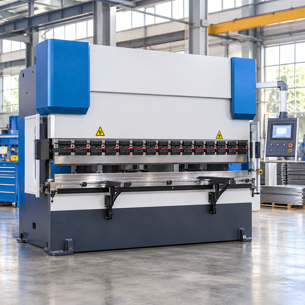
To see how these engineering principles translate into production hardware, examine the core architecture of the PSH Series Electro-Hydraulic Servo-Synchronous Press Brake.
Control Architecture and Closed-Loop Hydraulics
According to product data, the PSH series utilizes Delem or Cybelec CNC control systems paired with servomotors. These controllers regulate a 4+1 controlled axis layout consisting of the $Y_1$ and $Y_2$ ram cylinders, the $X$ backstop axis, the $R$ axis, plus a CNC-controlled crowning compensation system. Depending on the selected CNC configuration, the control may support tooling offsets, bend sequencing, and backgauge retraction across diverse component setups.
The hydraulic circuit integrates a complete Bosch proportional servo valve assembly featuring built-in overload protection and high-pressure filtration. With independent hydraulic disturbance compensation, the system regulates pressure distribution, allowing the machine to manage eccentric loads and maintain consistent multi-axis positioning accuracy. This ensures that uneven forming resistance across opposite bed ends does not compromise target flange angles.
Mechanical Bed Construction, Seals, and Crowning Mechanics
The PSH press brake frame is constructed from sand-blasted, rust-proof painted welded steel plates. To preserve structural alignment, the columns, working table, and upper slider are machined via floor boring mills, establishing mounting-surface parallelism and verticality. Machining these primary interfaces on large boring mills ensures that perpendicularity is maintained under heavy operational cycles.
Fluid sealing is handled by Japanese NOK and German ECO seals, paired with ball-screw and linear guideway mechanisms on the backgauge for accurate positioning. To address frame deflection across long spans, the lower bed incorporates a CNC-controlled slanting chisel crowning compensation system. Manual quick-clamp tool holders on the upper slider facilitate rapid punch changeovers, enabling rapid tooling reconfigurations between production jobs.
Verified Standard Series Parameter Ranges
The PSH series covers a broad operational envelope to accommodate diverse structural steel and sheet metal tasks. Across the standard product line, verified technical specifications encompass:
- Bending Force Capacity: 400 kN to 3200 kN (model dependent)
- Bending Length Range: 1500 mm to 6100 mm
- Distance Between Uprights: 1200 mm to 5400 mm
- Open Height Range: 390 mm to 540 mm
- Throat Depth Range: 220 mm to 400 mm
- Cylinder Stroke: 120 mm to 250 mm
- Main Motor Power: 4 kW to 22 kW
- Hydraulic Oil Tank Capacity: 120 L to 700 L
Standard series models include the PSH-40/1500, PSH-80/2500, PSH-100/2500, PSH-100/3200, PSH-125/3200, PSH-125/4100, PSH-160/3200, PSH-160/4100, PSH-200/3200, PSH-200/4100, PSH-250/3200, PSH-250/4100, PSH-250/5100, PSH-250/6100, PSH-320/3200, PSH-320/4100, PSH-320/5100, and PSH-320/6100. Specific per-model parameters should always be referenced directly from the manufacturer data sheets to match exact production requirements.
Industrial Workplace Safety and Operational Maintenance
Point-of-Operation Safeguarding Systems
Press brakes present inherent pinch hazards because operators routinely handle workpieces in close proximity to active forming tools. Ensuring operator safety requires a complete safeguarding system tailored to the equipment and plant regulations, combining presence-sensing devices, mechanical barrier enclosures, and certified operational interfaces designed to prevent unintended cycling.
- Presence-Sensing Devices: Optical safeguards, such as light curtains or laser-based presence-sensing devices, are commonly installed to monitor the zone immediately beneath the punch tip, arresting motion when an interruption occurs.
- Interlocked Physical Guards: Side and rear mechanical guards prevent personnel from entering backgauge travel areas or cylinder zones while the machine is active.
- Compliant Operational Controls: Foot pedals and two-hand control stations must be configured, shielded, and maintained in accordance with manufacturer instructions and relevant local workplace safety standards.
Preventative Maintenance Guidelines
Consistent preventive maintenance maintains part tolerances and protects mechanical, electrical, and hydraulic sub-assemblies. The following schedule serves as an illustrative maintenance checklist; operators must always follow the specific intervals in their machine operation manual:
- Daily Operational Checks: Inspect punch and die surfaces for wear, wipe the bed clean of debris to avoid crowning alignment errors, and confirm that hydraulic fluid levels match the sight gauge indicator.
- Periodic Drive Lubrication: Clean and grease the backgauge ball screws and linear guideways at regular intervals to maintain positioning accuracy and prevent mechanical binding.
- Hydraulic System Monitoring: Periodically inspect hydraulic lines, replace fluid filters according to duty cycle recommendations, and check fluid condition to protect proportional valve spools from contamination.
- Structural and Sensor Verification: Routinely inspect frame fasteners, check cylinder alignment, and verify sensor feedback signals to ensure consistent closed-loop operation across both cylinders.
Frequently Asked Questions (FAQs)
What is a press metal machine used for?
A press metal machine is deployed across manufacturing facilities to bend, fold, coin, or punch structural metal sheets and heavy plates into precise engineering components. Typical applications include fabricating automotive chassis members, high-precision electronics cabinets, commercial HVAC duct transitions, and industrial equipment enclosures. By applying controlled compressive force through specialized tooling, these systems deliver repeatable bend profiles across diverse sheet alloys without fracturing the material.
How does a press brake differ from a hydraulic stamping press?
A press brake uses universal, segmented punch-and-die sets along an open horizontal bed to execute sequential linear bends on varied part geometries, making it well-suited for high-mix batch work. A hydraulic stamping press uses dedicated, matched upper and lower closed dies to perform simultaneous stamping, deep drawing, or blanking cycles at rapid production rates, requiring significant upfront retooling investment for each part run.
How do I calculate the required bending tonnage for sheet metal?
Estimated air-bending force is calculated using the formula $F = (1.42 \cdot \sigma_b \cdot L \cdot t^2) / (V \cdot 1000)$, where $\sigma_b$ represents ultimate tensile strength in N/mm², $L$ is continuous bend length in millimeters, $t$ is thickness in millimeters, and $V$ is die opening in millimeters. This calculation yields a baseline engineering estimate that must always be validated against punch ratings, lower die capacities, and manufacturer tonnage charts.
What is the advantage of an electro-hydraulic servo-synchronous press brake over a torsion bar model?
Electro-hydraulic systems govern both cylinder axes ($Y_1$ and $Y_2$) independently through CNC proportional valves with continuous position feedback. This permits active ram leveling, precise angle correction, and better stability during off-center loading compared to mechanical torsion-bar designs. The independent hydraulic circuits allow dynamic compensation for variable plate resistance across the bed, whereas torsion bars rely on a fixed mechanical linkage that resists individual cylinder adjustment.
What do the Y1, Y2, X, and R axes control on a CNC press brake?
The $Y_1$ and $Y_2$ axes control the independent vertical positioning and stroke depth of the left and right hydraulic cylinders on the upper ram. The $X$ axis positions the backgauge fingers horizontally front-to-back to establish accurate flange dimensions, while the $R$ axis adjusts the backgauge fingers vertically to accommodate different lower die heights and stepped profile geometries during sequential bending steps.
Why is bed crowning necessary when bending long sheets?
Under load, the upper ram flexes slightly upward while the lower bed deflects downward. This deflection causes the punch to penetrate shallower in the center than near the side frames, resulting in wider bend angles in the middle. Bed crowning introduces a compensating upward contour along the bed to maintain uniform punch penetration along the entire working length of the workpiece.
Matching Machine Capabilities to Production Goals
Choosing the right press metal machine boils down to evaluating material thickness, required bend accuracy, and part mix. While simpler bending tasks can be handled on basic equipment, demanding industrial fabrication benefits from the closed-loop control and flexibility of electro-hydraulic servo systems. Specifying precision components—such as proportional hydraulic valves, advanced CNC interfaces, and slanting chisel crowning—helps workshops hit design tolerances, minimize scrap, and maximize operational throughput across every shift.
Investing in a modern CNC press metal machine requires aligning mechanical capacity with realistic fabrication demands. Sizing the machine’s daylight, stroke, throat depth, and multi-axis backgauge automation correctly enables facilities to accommodate evolving part catalogs without encountering frame interference or tonnage bottlenecks. Ultimately, selecting equipment built with rigid structural frames and synchronized hydraulics delivers the consistency, flexibility, and operational safety needed to maintain a competitive manufacturing edge.
-
Press Metal Machine: Complete Engineering Guide to Types, Selection, and CNC Press Brake Specifications
2026/11/13 -
Choosing HVAC Duct Folding Machines for Flange-Safe Bending
2026/10/13 -
Precision Metal Forming Machines: What Separates Accurate Bends From Scrapped Sheet
2026/10/12 -
What to Look for in an HVAC Folding Machine Manufacturer
2026/10/11
-
Sheet Metal Press Brake: Ultimate Guide to Precision Bending Technology in 2024
2026/03/13 -
Metal Punching Machine: Ultimate Guide to Precision Manufacturing in 2024
2026/03/11 -
Metal Folding Machine: Comprehensive Guide to Precision Bending in 2024
2026/03/09 -
Sheet Metal Equipment: Ultimate Guide to Industrial Fabrication Solutions in 2026
2026/03/06
-
A Guide to the Latest Innovations in Sheet Metal Folding Machines
2024/11/29 -
Key Features to Consider When Investing in a Sheet Metal Folding Machine
2024/11/28 -
Enhancing Precision with Advanced Sheet Metal Folding Machines
2024/11/27 -
How to Choose the Right Sheet Metal Folding Machine for Your Workshop
2024/11/26
